


Tools Needed:
1.六角钥匙2.5毫米
2.十六进制密钥3.mm
3.. Filip Screw Drive
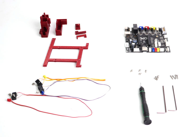
| cetus mk2to MK3 Part List BC0881 | ||||
| item | 斯科 | 姓名 | Spec | QTY. |
| 1 | 25.0.0.7. | T-坚果 | M3×10mm | 2 |
| 2 | 25119 | 电缆潮汐 | 64mm,可调节表带 | 1 |
| 3. | BC0751 | MK3 Mainboard | 1 | |
| 4. | 04151. | 平头自钻菲利普螺丝 | ST2.5 * 8. | 6. |
| 5. | 04158. | sunk head philip screw | M3×5 | 10. |
| 6. | 041107 | sunk head philip screw | M2.5 * 12. | 8. |
| 7. | 04157. | sunk head philip screw | M3*8 | 8. |
| 8. | 40060. | 六角螺丝 | M3×12 | 2 |
| 9. | 25547 | X limit switch with cable | 电缆:400mm.那2P blue connector | 1 |
| 10. | 25548 | y利用电缆限制开关 | cable:300mm,2P red connector | 1 |
| 11. | 25549 | Z利用电缆限制开关 | 电缆:250mm,2p黄色连接器 | 1 |
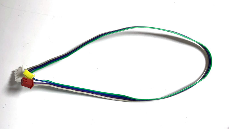
| 12. | 25550. | YZ限制SWITHC继电器电缆 | cable:330mm | 1 |
| 13. | 25554 | 主板地线 | 5pin×80mm. | 1 |
| 14. | BC0872 | 推广PCB套件 | 1 | |
Other Required Components :
After upgrade, if user install the heated build platform, original power supply cannot be used to supply power to the machine. User have to use the 220W Power Supply (sku:XS028).
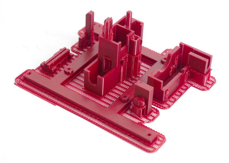
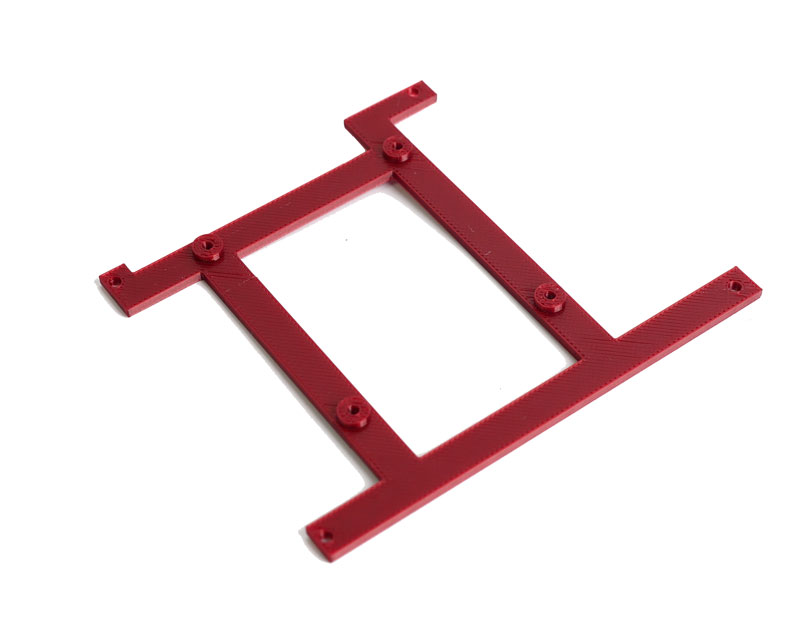
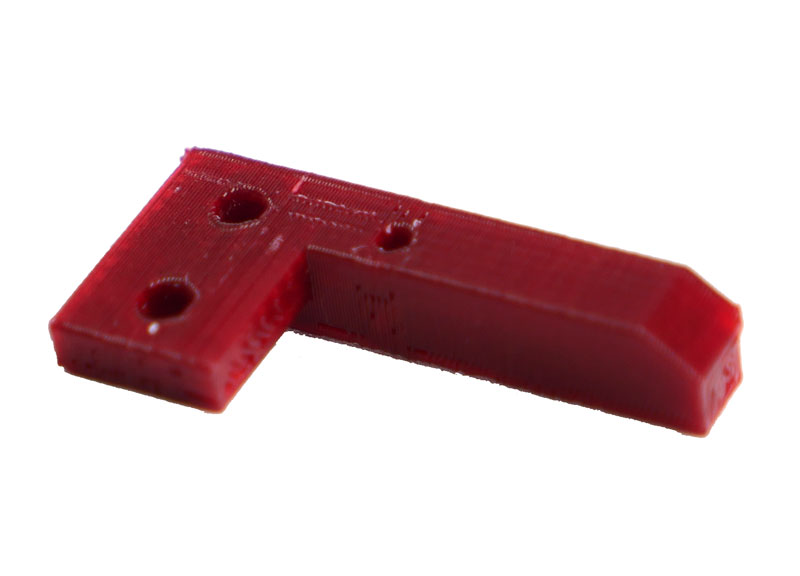
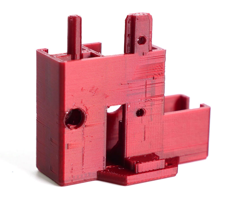
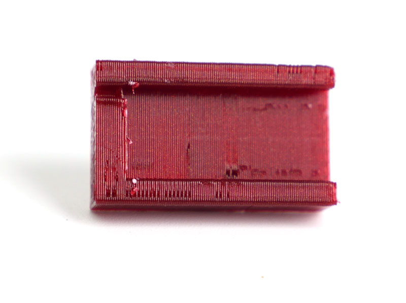
步骤1.打印升级所需的塑料部件
在解除所有内容之前,打印出所需的部件。
下载可打印部件的以下文件:
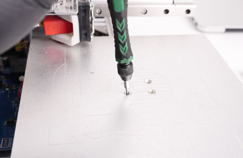
步骤2.对机器不干。
2.1. Remove the platform by removing the 3 scerws.
2.2将4个螺钉拆下到机器底部。
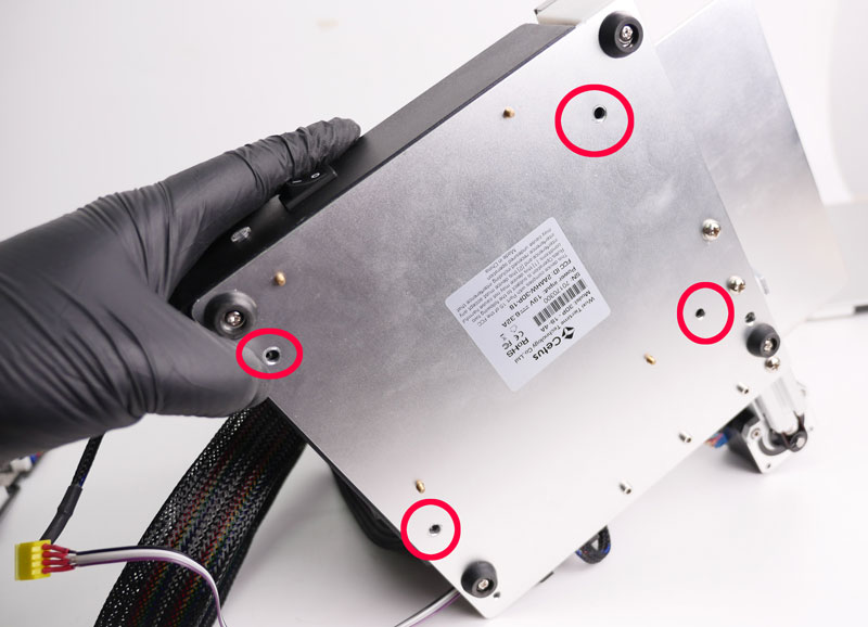
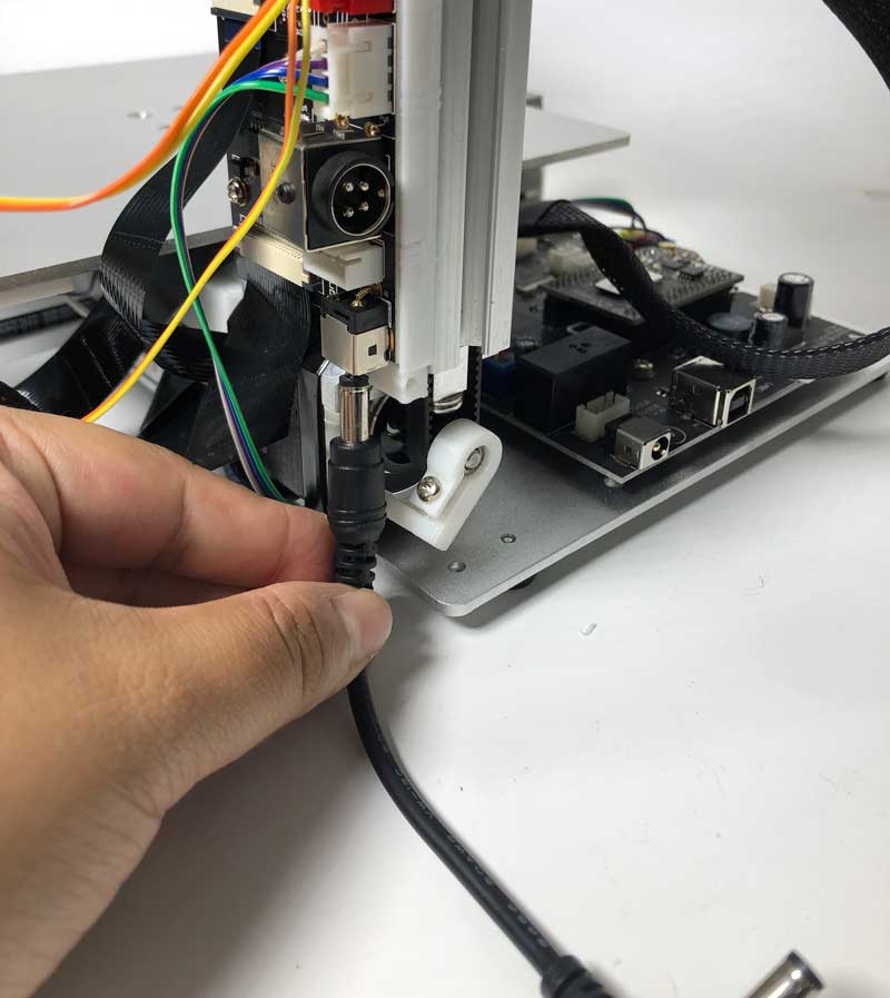
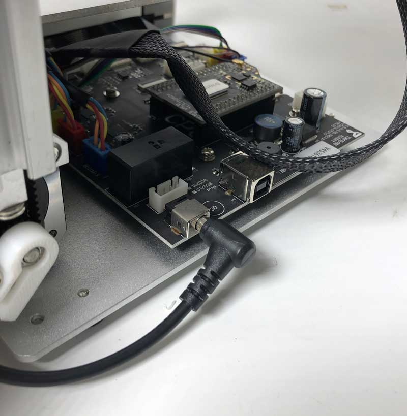
2.3。卸下电源线和初始化按钮电缆。
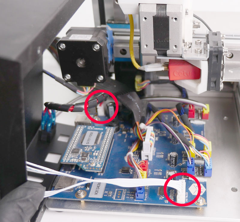
2.4。删除CPU。删除之前的CPU, discharging yourself is recommended, also be careful not to bend the pin of the CPU board.
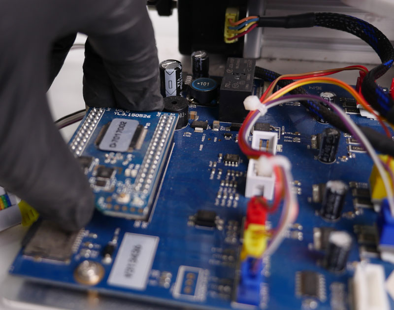
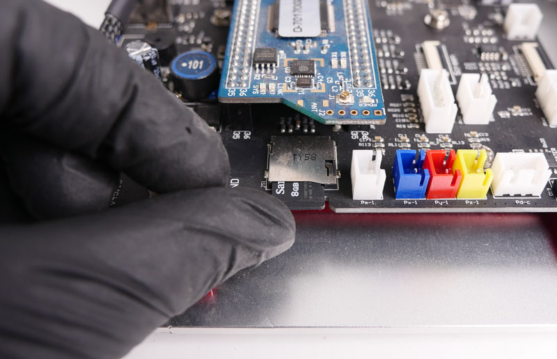
2.5。在主板上卸下SD卡。

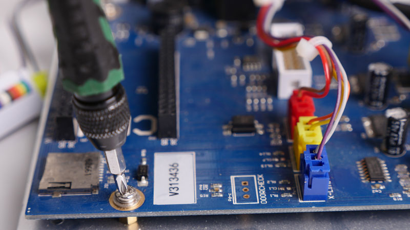
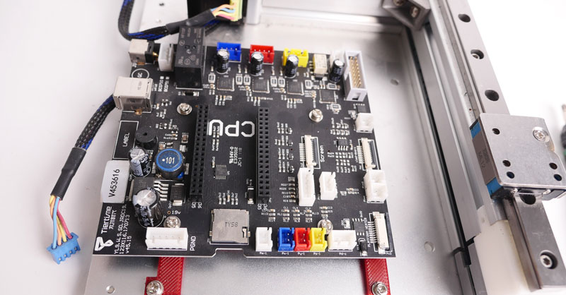
2.6. Remove the 4 screws on mainboard, unplug the extruder cable, motor cables and remove the mainboard.
步骤3.安装MK3主板。
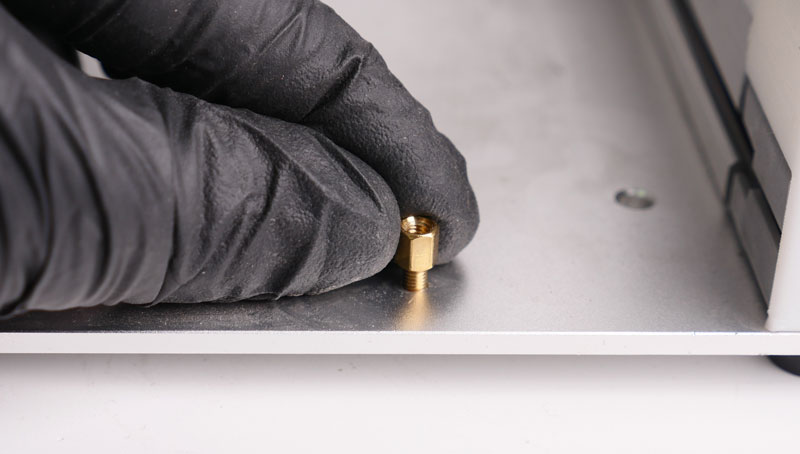
3.1用手取出黄铜螺母
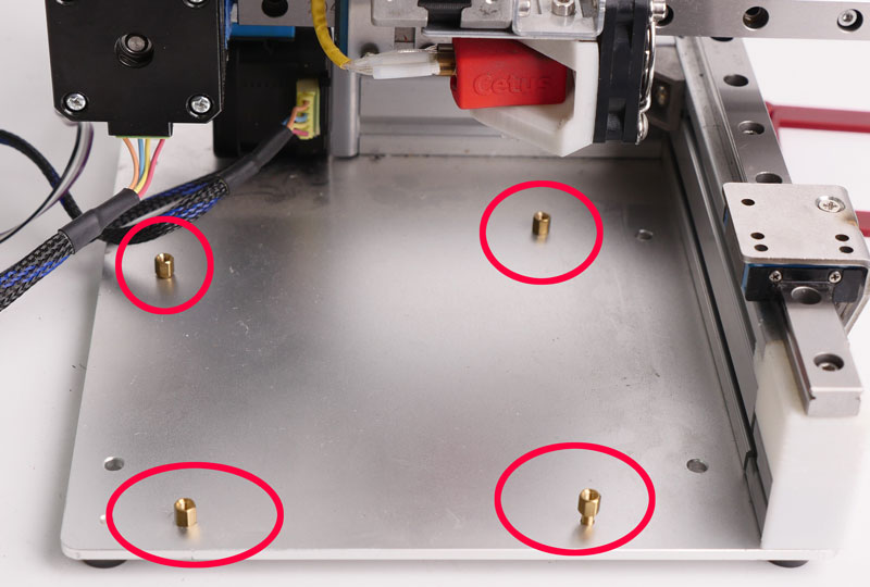
3.2安装主板适配器和MK3主板。
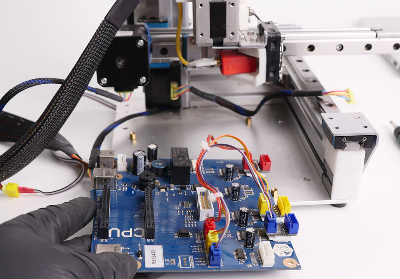
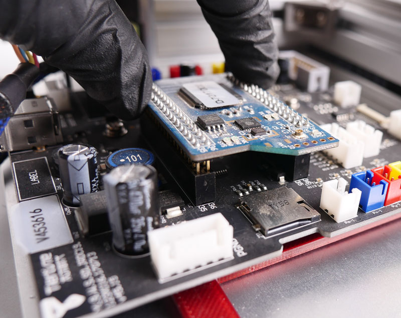
3.3。安装MK3主板,CPU和SD卡。
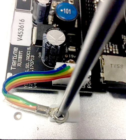
3.4。连接地电缆(将静电充电损坏的风险降低到电子产品)
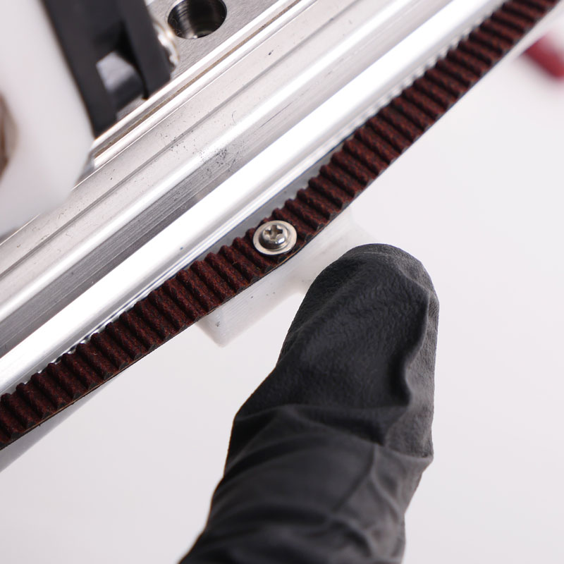
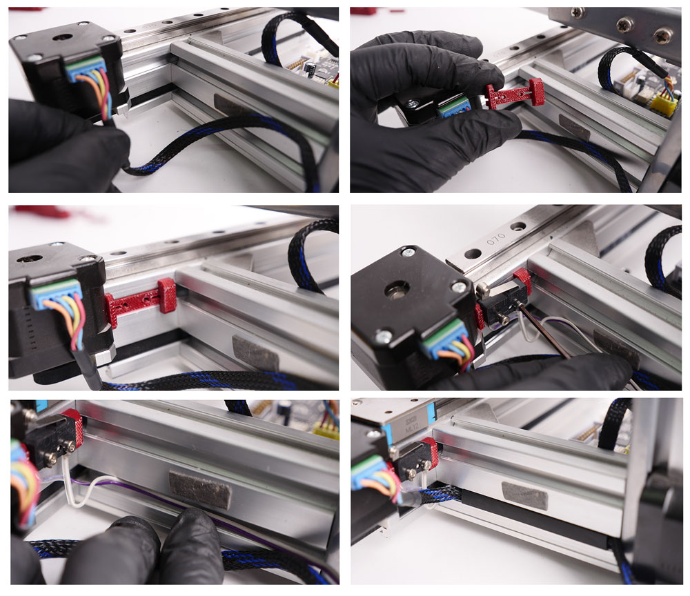
步骤4.安装Y轴限制开关和触发器。
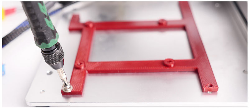
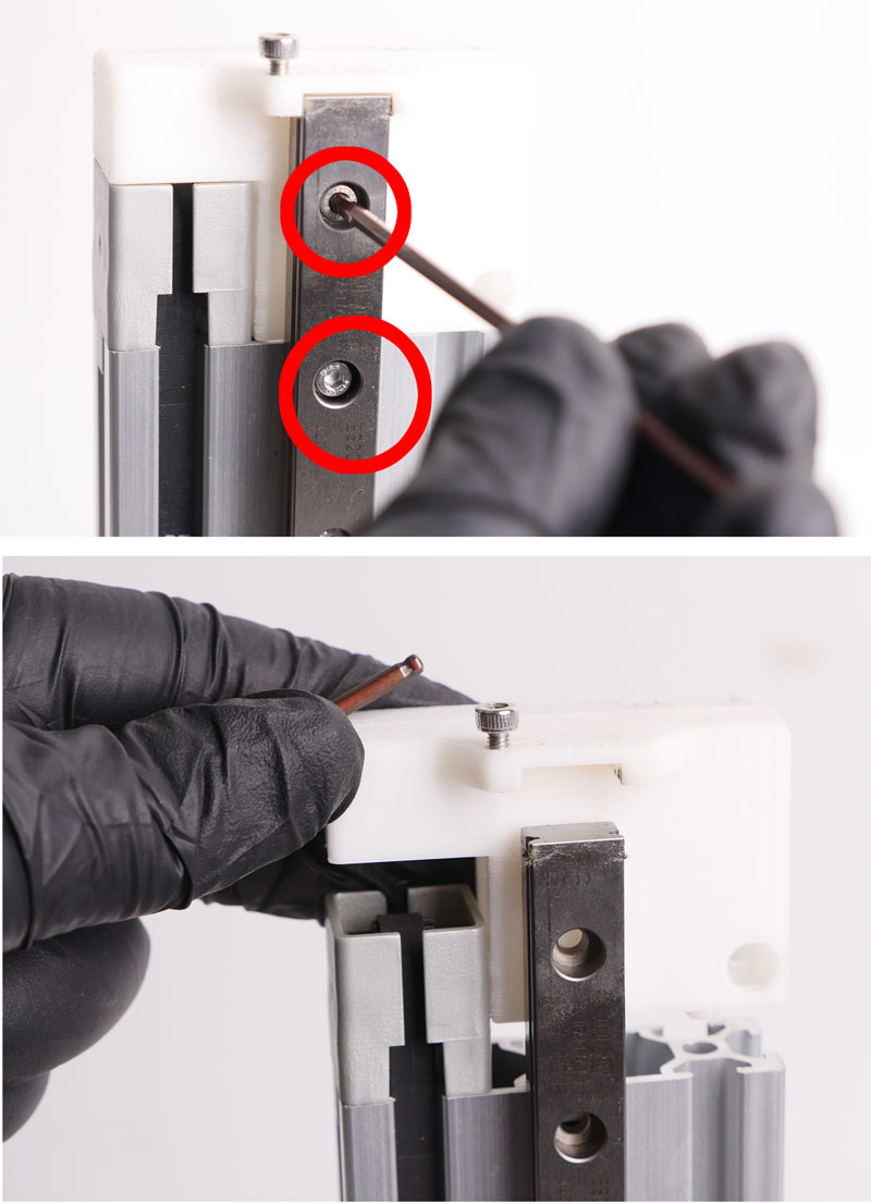
4..1. Remove the Screws
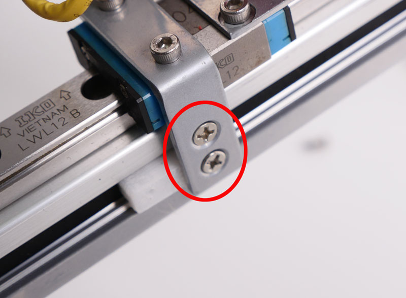
Expose the original Y-trigger
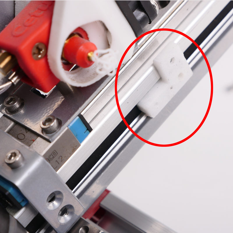
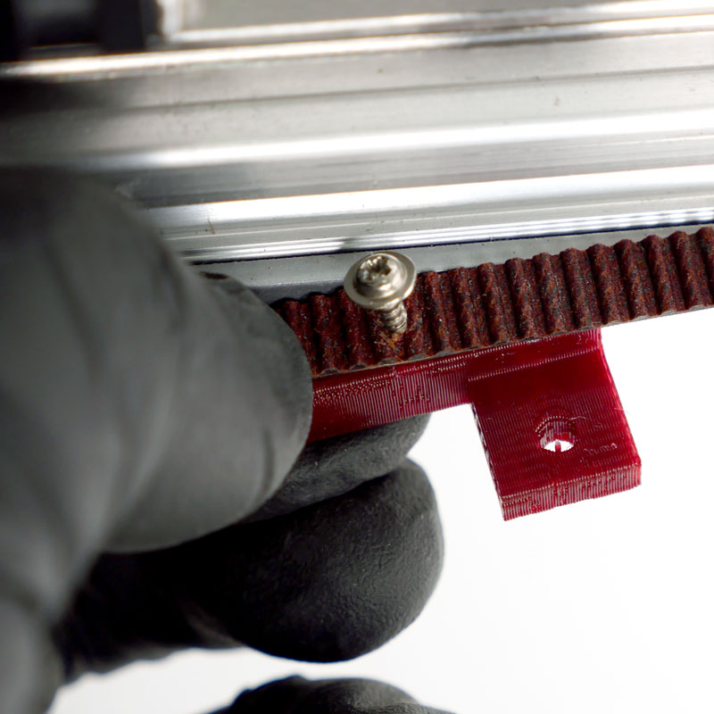
4..2. Lossen the screw on the back of the belt, remove the printed part.不要从皮带上取下螺钉,将其保持在皮带上!
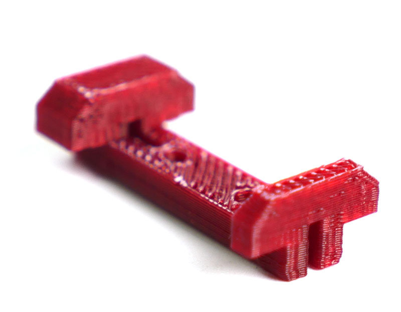
4.3。安装新的Y限制开关触发器
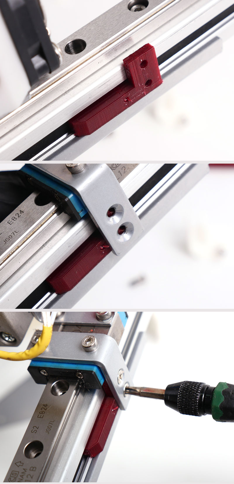
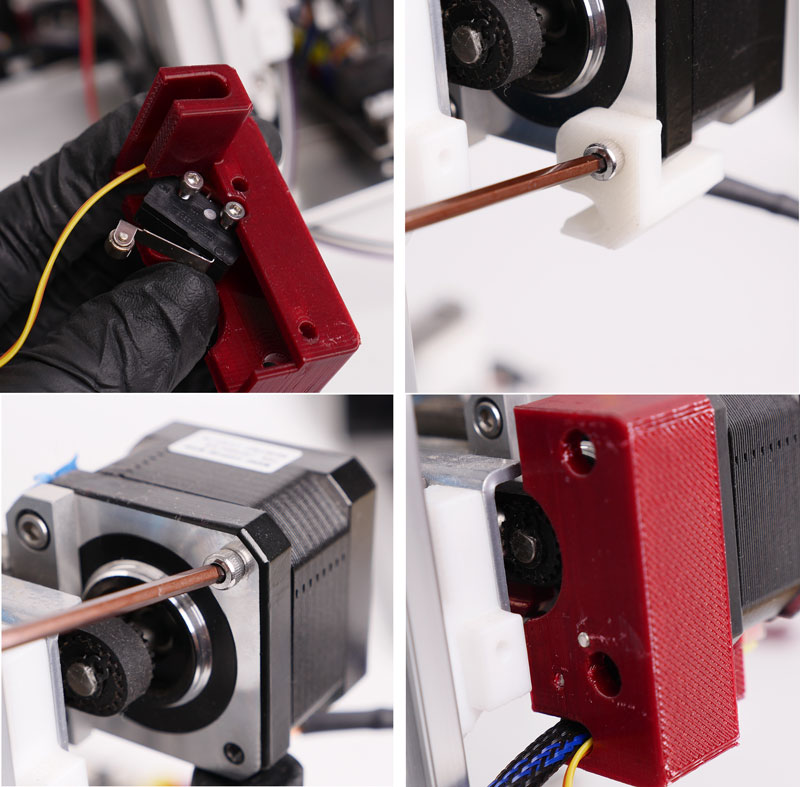
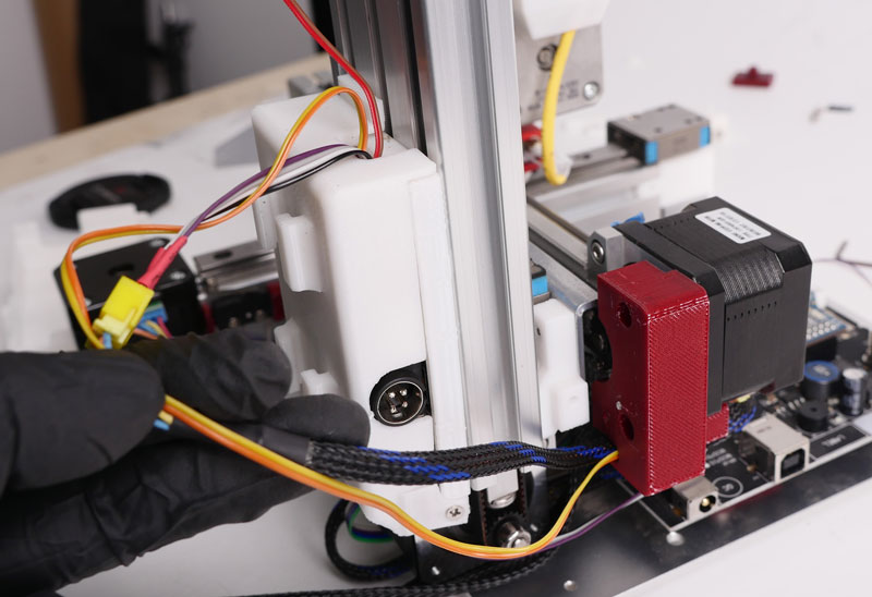
Step 5. Install the Y-axis Limit Switch
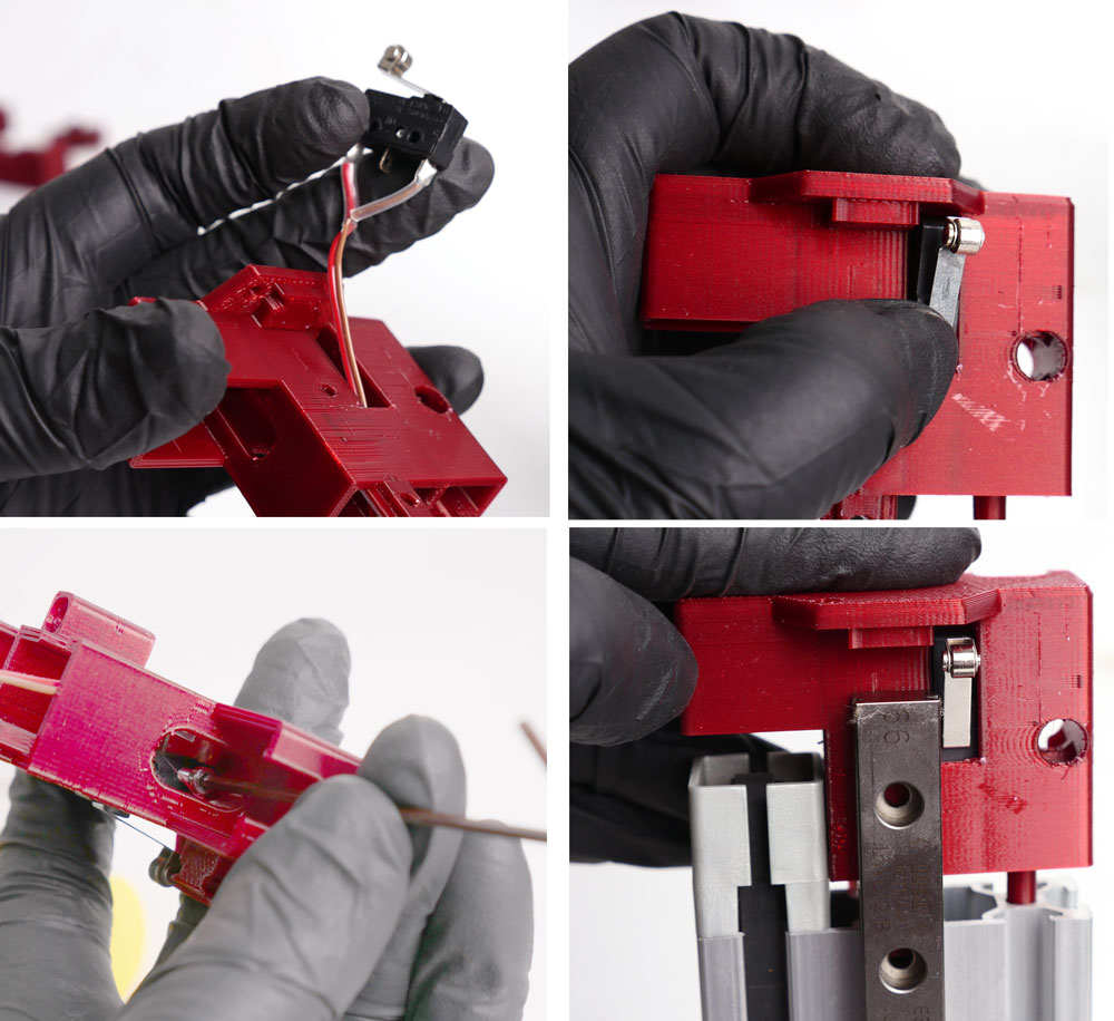
5.1。在持有者上安装限位开关。
5.2。拆下电机上的原始印刷部件和螺钉。
5.3。将限位开关支架安装到Y轴电机上。
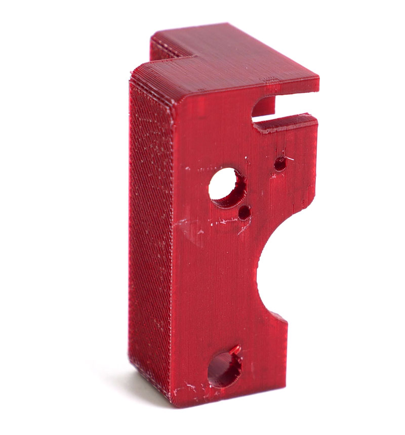
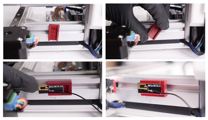
步骤6.安装X轴限制开关
X-axis Limit Switch Holder
6.1打开打印机背面的插槽盖。
6..2 Press the holder into the slot, install the limit switch.
6..3 Position the motor cable and limit switch cable into the slot and press fit the slot cover.
步骤7.安装扩展PCB
也可能指的是follwoing文章:
Chapter 4. Installation Guide of Extension PCB for Cetus MK3
7.1卸载z帽
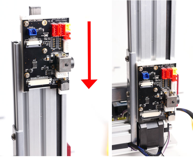
7.2将扩展板滑入挤出插槽。
Step 8. Install MK3 Z-axis Cap and Limit Switch.
8..2 Install the Z-axis Limit Switch.
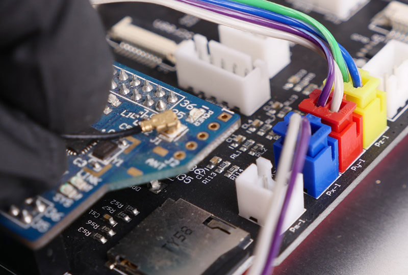
Step 9. Connecting the Cables
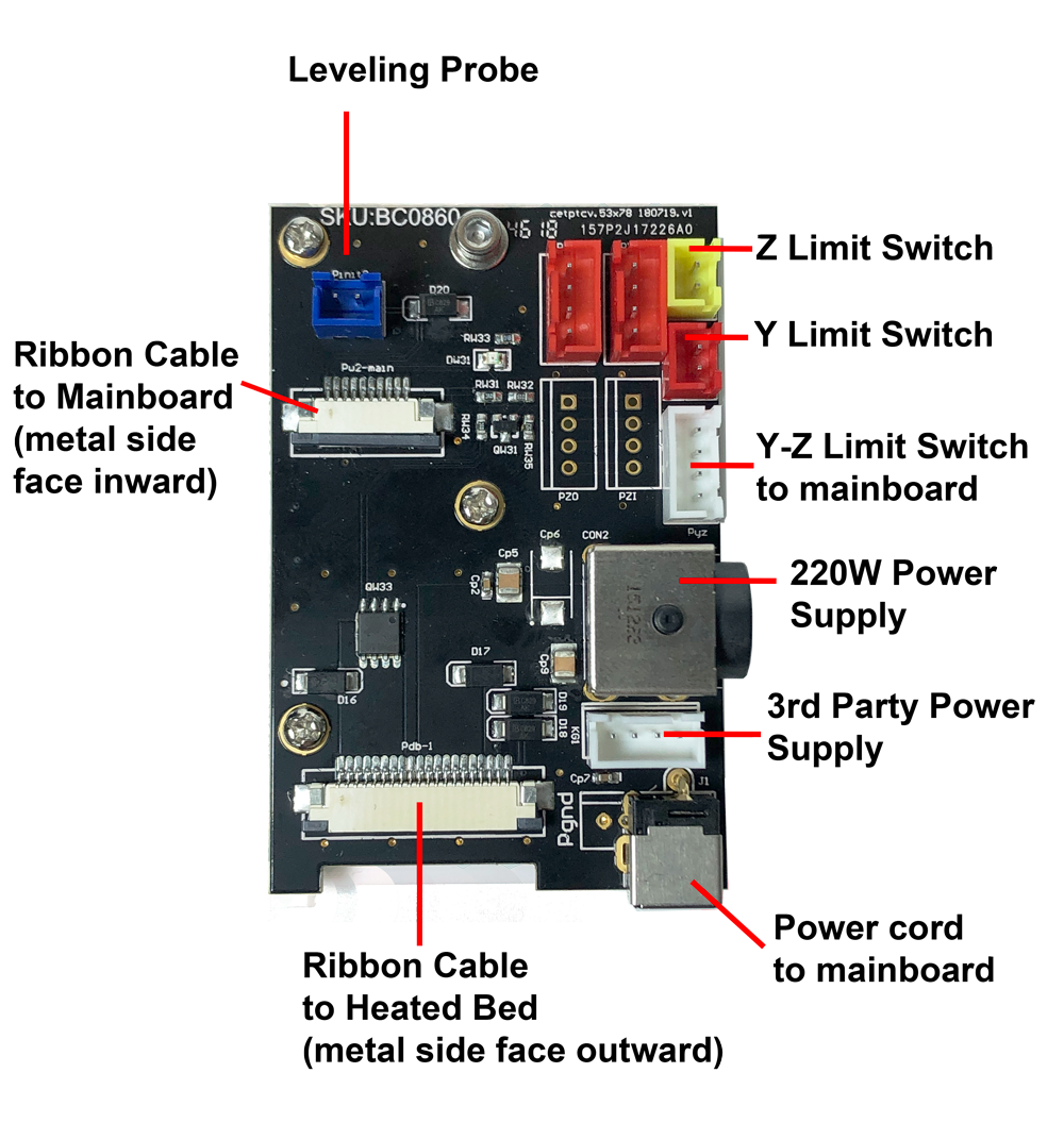
9.1连接Z-LIMIT开关和y限制开关到扩展板。遵循颜色。
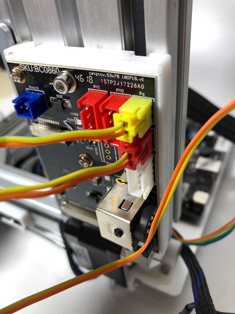
9..2 Connect the limit switches from extension PCB to mainboard, using the included relay cable.
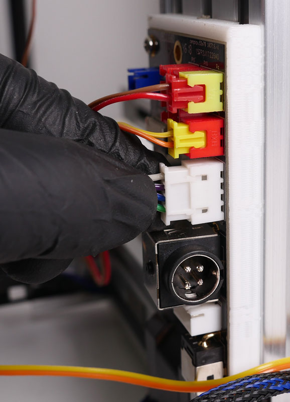
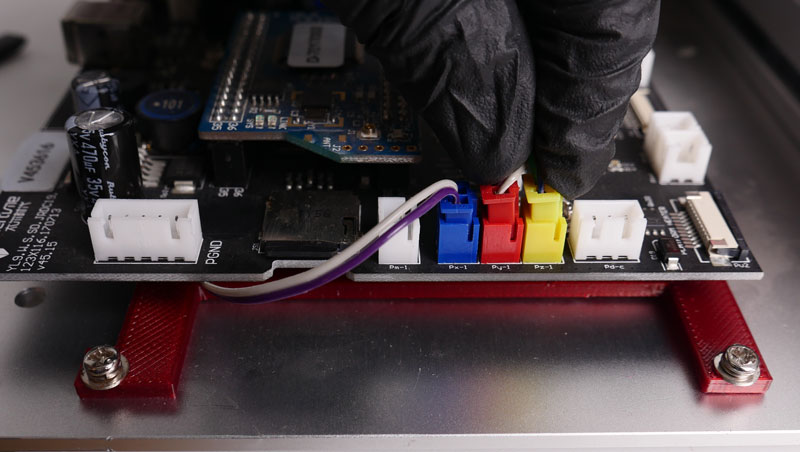
9..3 Connect the power cable from extension PCB to mainboard
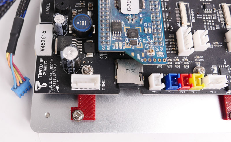
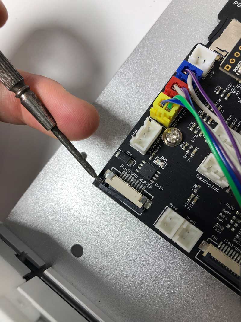
9..4 Loosen the connector (labelled as " Platform Heater) for ribbon cable. Insert the cable into the connector, metal pins facing to mainboard.
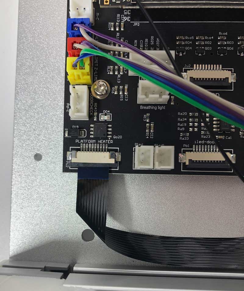
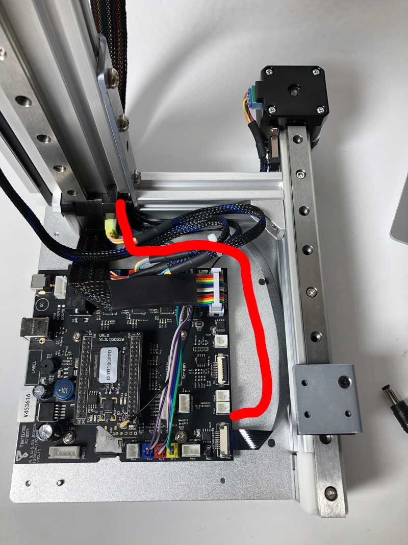
9.5将电缆折叠成形状,如下面所示的红线。
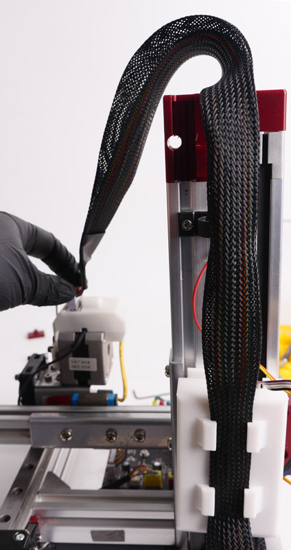
9..6 Insert the ribbon cable through the space between motor and Z-axis bracket.
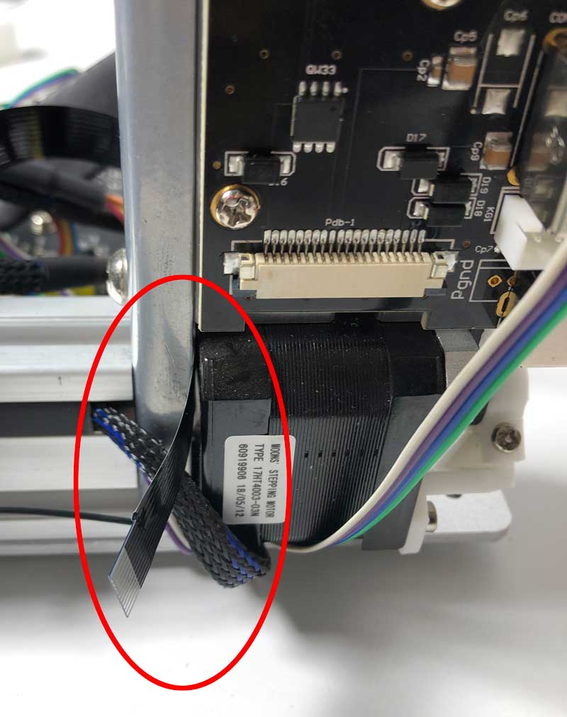
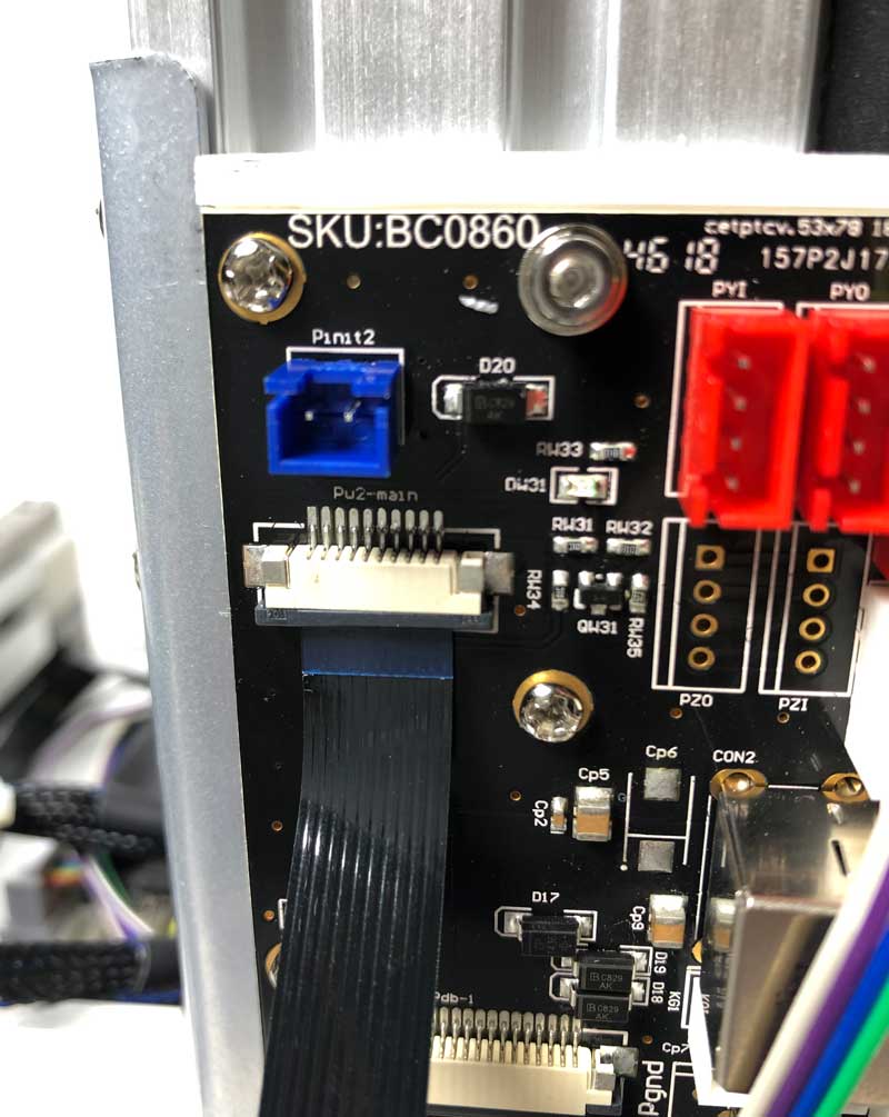
9.7向上折叠电缆并插入连接器,朝向延伸板的金属销。
这种带状电缆对于加热床升级和自动螺纹的温度控制很重要。
Step 10. Install Wifi antenna
10.1将天线支架插入机器背面的插槽中,将其转动90度以将其锁定到位。
10.2将天线插入支架并将另一端连接到CPU。
10.3确保电缆完全分类,没有缠结。安装PCB封面。
10.4。锁定PCB盖子。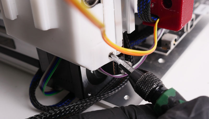
10.5。沿Z轴锁定挤出机电缆
Step11. ROM Update:
CPU rom must be updated before the machine is usable, please refer to following info to update your rom.
| MK3 Standard Version ROM: | cetus s7ntc_r_180524 mk3-std.rom |
| MK3扩展版本ROM: |
Step 13. Instruction for Installing True Touch Calibration Probe
Comments
9评论
MK1也可以使用这个套件吗?
I've had problems installing the upgrade:items 5 & 7 in the kit differ from the spec above; the ground wire is different (no 5 way plug to attach to PCB), and the USB/power sockets won't align to the holes in the case if the brass standoffs are mounted on the mainboard adapter as shown above - it looks like the board either needs to mount directly to the adapter, or the standoffs need to be moved to new drilled&tapped holes in the base plate, and the adaptor discarded. I'll submit a support request - not sure if these comments are monitored.
Tiertime会给Windows发出签名驱动程序吗?
我已经完成了硬件升级,但现在无法升级ROM,因为Windows没有正确的驱动程序。我尝试从网站下载驱动程序,但这些仍未签名,因此不会安装。
Turning off the Widows security features to force the installation is not a desirable solution.
Hi the kit has different bugs:
1. 3D印刷部件不正常
https://support.tiertime.com/hc/article_attachments/360042023454/upgrade_parts.up3
for the z axis I had to use the original cap to make a hole for the endstop because the linear rail from my printer seems to be shorter (the black part is the new one from the link above (didn't fit).
when the Mainboard was installed it was too close to the baseplate edge so that I could not put the Cover back on again. Therefore I hab to drill 4 more holes in the Baseplate to shift the Mainboard about 5mm to the middle.
after installing all the hardware I flashed the CPU with
https://support.tiertime.com/hc/en-us/article_attachments/360042033694/Cetus_S11NTC_R_180524_MK3-EXT.ROM
似乎工作......但是......硬件init开关不再工作了!!!!!!
init软件正在工作,endstops也在运行。
但那不是全部!
when I wantetd to print the first time (alfter leveling of course) the Nozzle first cleans (one straight line) which was ok. But when starting the first raft-layer-line the nozzles seems to dig into the printbed.
y and z axis move simultaniously.
https://youtu.be/xE2j11haqVQ
所以我不知道是什么错了,我需要支持
I have the same problem with the base cover. Is this the only solution? Printing is fine though.
这个对我有用:mainboard adaptor plate (remix)
和:我直接在适配器上安装了电路板。
似乎他们忘了从PCB中取出V-Groove边缘轨道。在用原始适配器仔细使用钳子仔细拆除它们后,PCB在壳体中非常适合。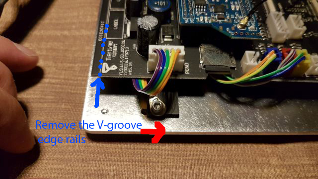
在闪烁尝试后,我无法获得任何工作。它只花了1秒,所以我不认为它闪过新的固件。有人吗?
我有问题,即闪烁ROM后,连接瞬时开关并在上面做Evrytsth(加上的调整),打印机忽略了Z轴止动器中的右转。在Up Studio软件中有一个系统错误,使用错误消失的实用程序软件重新安装ROM后。问题仍在那里。请帮忙
请登入留下评论。